GPS tracking based on LoRa 169/433/868/915 Mhz
Release time:2019-12-02

Connection : USB - Serial
Need : Chrome Browser
Need : 1 X Arduino Mega
Need : 1 X GPS
Need : 1 X SD card
Need : 2 X LoRa Modem
Function: Arduino Send GPS value to main base - Main base store data in Dataino
Server
Lora Module: Ultra long range RF1276 from APPCONWIRELESS
LoRa is a new, private and spread-spectrum modulation technique which allows
sending data at extremely low data-rates to extremely long ranges. The low
data-rate (down to few bytes per second) and LoRa modulation lead to very low
receiver sensitivity, means in this test means more than 10km.
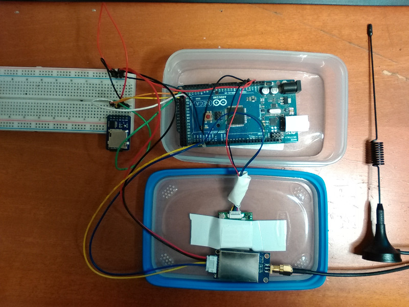
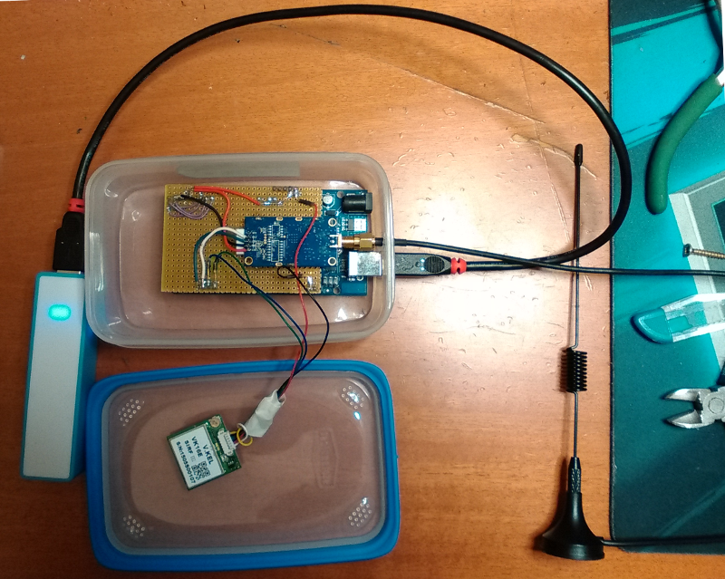
· 1 - Base Station
Computer width internet connection and a LoRa modem connected into USB port .
Arduino Car Kit
· The metric box
Anduino Mega connected to serial 2 to GPS reciver, and Serial 1 to LoRa
modem.
A SD card is used for store data.
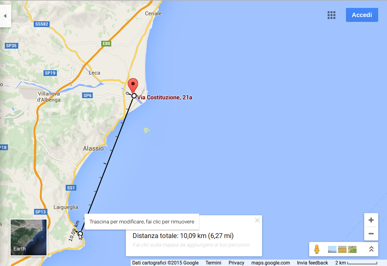
The first test
· 10.6 Km on a path through urban centers, galleries and along the coast made with loops
The ratio of reception /transmission has been of 321/500
TX point
RX point
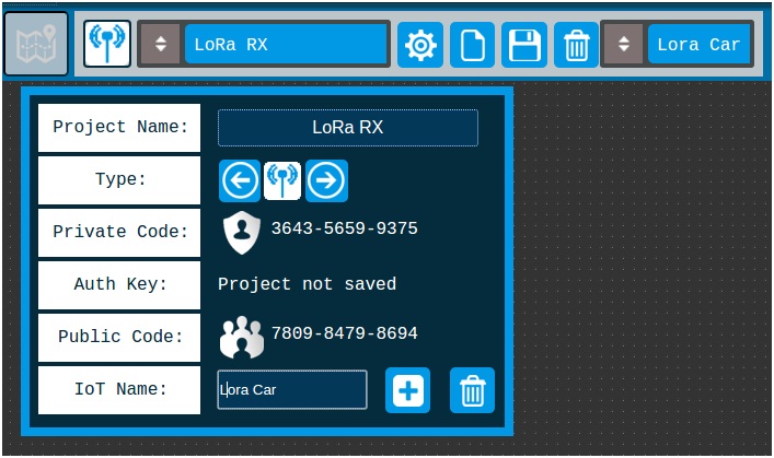
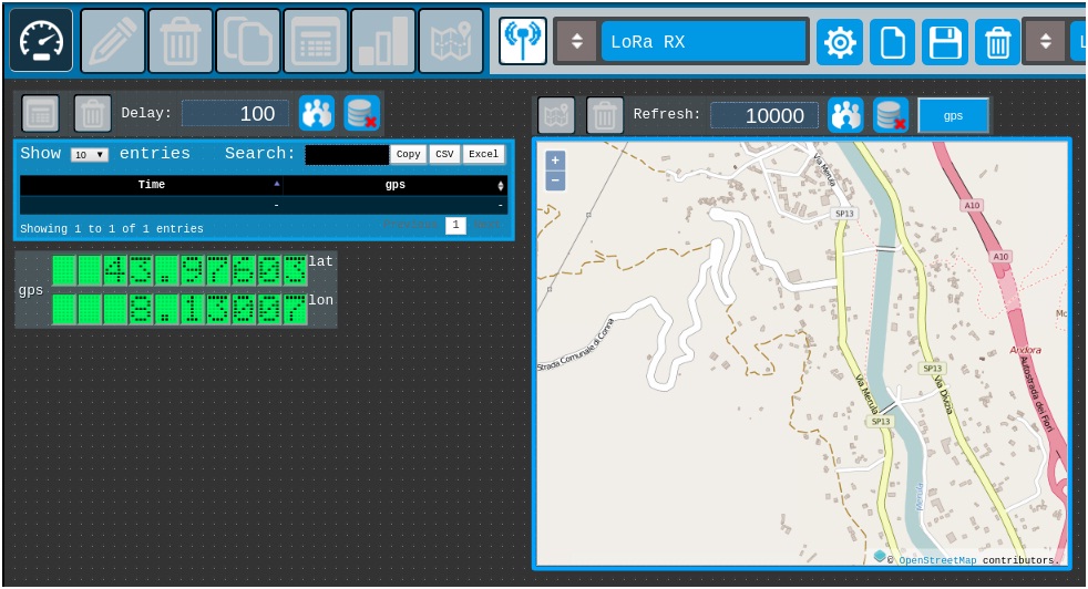
Create the Interface
· 1 - Set up a new project LoRa
Press icon cog to open project config
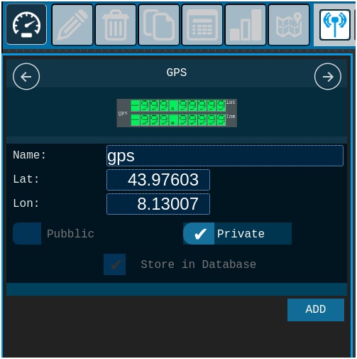
Add Gauge
·
2) Open the gauge slider.
· 3) Scroll to the GPS.
· 4) Add one to the desk.
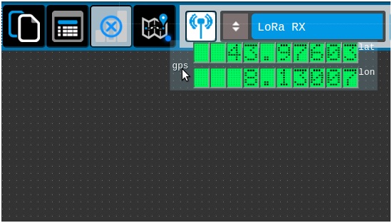
Drag gauge GPS and add OpenStreetMap
· 5) Add OpenStreetMap map to desk
Dragging the component GPS on the icon map, OpenStreet map is generated.
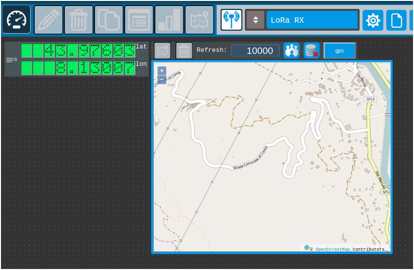
Create the Interface
· 6) Change map refresh
Change the map refresh time from 5000 to 10000
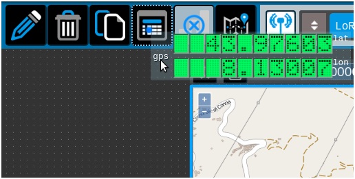
Drag GPS gauge and add table log
· 7) Add a Table Log gauge.
By dragging the gauge above the GPS icon table is created gauge table log
· 8) Change table log refresh.
Change the map refresh time from 5000 to 10000
Adjust the position of the gauges
· 9) Drag gauges
adjust the position of the gauges by dragging them across the screen.
· 10) Save project
Get code
· 10) Activate code container
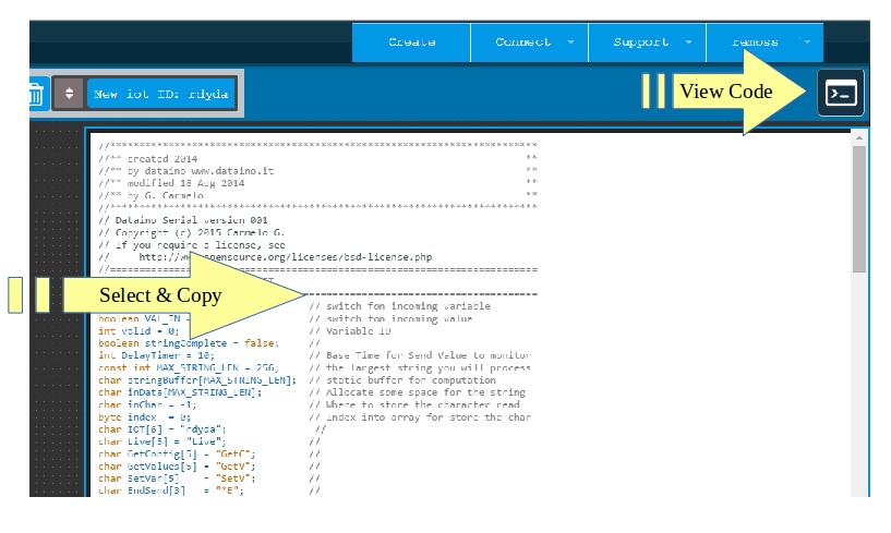
Button on top right button, select all and copy base code.
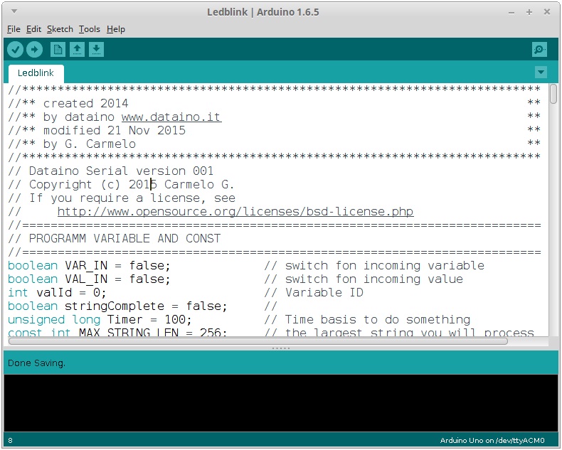
Arduino IDE
· 11) Paste code on Arduino IDE
· 12) Edit code
Add this line in the definition
//*************************************************************************
//** LIBRARY **
//*************************************************************************
#include <TinyGPS.h> // ++ GPS library
#include <SPI.h> // ++ SPI library
#include <SD.h> // ++ SD library
//*************************************************************************
//** SD **
//*************************************************************************
// * SD card attached to SPI bus as follows:
// ** UNO: MOSI - pin 11, MISO - pin 12, CLK - pin 13, CS - pin 4
// (CS pin can be changed) and pin #10 (SS) must be an output
// ** Mega: MOSI - pin 51, MISO - pin 50, CLK - pin 52, CS - pin 53
// (CS pin can be changed) and pin #52 (SS) must be an output
// ** Leonardo: Connect to hardware SPI via the ICSP header
// Pin 4 used here for consistency with other Arduino examples
const int chipSelect = 53; // ++ SD pin selector
//*************************************************************************
//** GPS **
//*************************************************************************
TinyGPS gps; // ++ GPS on Serial2
void gpsdump(TinyGPS &gps); // ++
bool newdataGPS = false; // ++
Add this line in the setup()
//***********************************************************************
//** GPS serial setup **
//***********************************************************************
Serial2.begin( 9600 ); // ++
delay( 1000 ); // ++
//***********************************************************************
//** SD Initializing **
//***********************************************************************
// make sure that the default chip select pin is set to // ++
// output, even if you don't use it: // ++
pinMode( SS, OUTPUT ); // ++
Serial.println( F("Initializing SD card...") ); // ++
// see if the card is present and can be initialized: // ++
if (!SD.begin(chipSelect)) { // ++
Serial.println( F("Card failed, or not present") ); // ++
// don't do anything more: // ++
return; // ++
} else { // ++
Serial.println( F("SD card OK") ); // ++
} // ++
Add this lines in loop() void
serialEvent2(); // ++ call GPS serial event
Add SeriaEvent2 code
//*************************************************************************
//** GPS serialEvent **
//*************************************************************************
void serialEvent2() { // ++
while (Serial2.available()) { // ++
char c = Serial2.read(); // ++
//Serial.print(c); // uncomment to see raw GPS data // ++
if ( gps.encode(c) ) { // ++
newdataGPS = true; // ++
break; // uncomment to print new data immediately! // ++
} // ++
} // ++
} // ++
Add GPS dump voud
//*************************************************************************
//** gps dump **
//*************************************************************************
//** The valid range of latitude in degrees is -90 and +90 . **
//** Longitude is in the range -180 and +180 **
//** specifying the east-west position **
//** "123456789 1234567890" **
//** "000.00000;0000.00000" **
//*************************************************************************
void gpsdump(TinyGPS & gps) // ++
{ // ++
int year; // ++
byte month, day, hour, minute, second, hundredths; // ++
unsigned long age; // ++
gps.f_get_position( &LATGP00, &LONGP00, &age ); // ++
gps.crack_datetime( &year, &month, &day, &hour, // ++
&minute, &second, &hundredths,
